Research publication · Aeronautical nondestructive evaluation
TerahertzTerahertz radiation is electromagnetic energy commonly associated with frequencies around 0.1 to 10 THz, between microwaves and infrared, where many materials reveal distinctive propagation, absorption, and imaging behavior. More waves for contactless control and imaging in aeronautics industry
Aeronautical inspection spans very different scales: a maintenance team may need to locate an object or defect behind a composite panel, while a coating process requires control of layers only tens of micrometres thick. This paper addresses both problems with complementary terahertzTerahertz radiation is electromagnetic energy commonly associated with frequencies around 0.1 to 10 THz, between microwaves and infrared, where many materials reveal distinctive propagation, absorption, and imaging behavior. More approaches. Frequency-modulated continuous-wave radars at millimetre and sub-terahertz frequencies provide range-resolved images through dielectric structures. TerahertzTerahertz radiation is electromagnetic energy commonly associated with frequencies around 0.1 to 10 THz, between microwaves and infrared, where many materials reveal distinctive propagation, absorption, and imaging behavior. More time-domain spectroscopy, coupled to an iterative model, analyzes the multiple reflections in a painted metal stack. The demonstrations show contactless access to internal interfaces and coating parameters in laboratory configurations. They do not constitute qualification for aircraft service, where geometry, environmental variation, inspection cadence and defect probability would require dedicated validation.
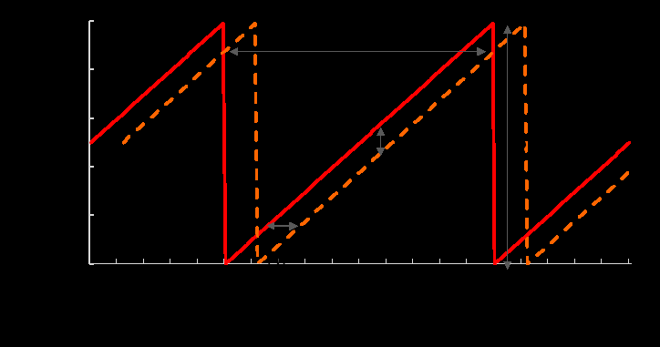
FMCW radarFMCW radar transmits a continuously swept frequency and measures the beat signal produced by delayed reflections, enabling distance, thickness, and depth-resolved imaging with compact coherent hardware. More measures distance by sweeping frequency and mixing the returned signal with a reference copy of the transmitted chirp. The delay introduced by propagation becomes a beat frequency, so each reflecting interface appears at a different range. A broad sweep improves longitudinal resolution, while operating frequency and focusing optics set the lateral spot. For composites, there is an unavoidable balance: higher frequencies can distinguish smaller details but are generally attenuated more strongly and penetrate less deeply. The article evaluates systems around 100, 150, 300 and 600 GHz to frame that choice rather than presenting one band as optimal for every aircraft structure.
Paint inspection poses another inverse problem. A terahertzTerahertz radiation is electromagnetic energy commonly associated with frequencies around 0.1 to 10 THz, between microwaves and infrared, where many materials reveal distinctive propagation, absorption, and imaging behavior. More pulse incident on varnish, colour coats, primers and metal divides at every boundary. The measured waveform contains direct returns and many weaker paths that have reflected several times inside the stack. A complete model rapidly becomes large as the number of layers increases. The authors introduce an iterative tree algorithm to identify which paths materially affect the waveform and retain those contributions in a reduced transfer function. The radar and time-domain studies are linked by the same physical principle, namely the use of delayed reflections, but they target different depths, materials and measurement regimes.
Featured visual: Image 1 from the Airtable record associated with this publication. Consult the original paper for the authoritative figure caption and interpretation. Source publication.
Visuals are drawn from the Airtable research archive. Figure numbering, rights and interpretation should be checked against the original publication before republication outside this site.
Range-resolved imaging through aeronautical structures
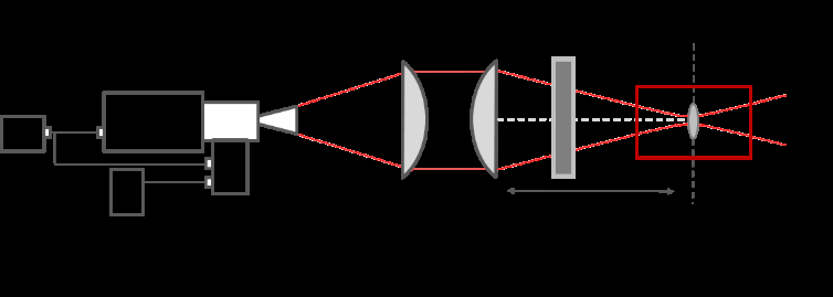
The radar architecture starts with a voltage-controlled oscillator whose sawtooth sweep is multiplied into the desired band. A quasi-optical arrangement of Teflon lenses focuses the beam and collects the return. The researchers scanned glass-fibre-reinforced polymer panels and carbon-fibre composite structures, then reconstructed two-dimensional maps and three-dimensional range volumes. As expected, the 300 GHz instrument offered finer lateral and depth resolution, while the 100 GHz system retained greater penetration and dynamic range through the tested dielectric panel. Carbon-rich materials remain particularly challenging because conductivity and absorption can suppress the field before it reaches a buried interface.
In a see-through experiment, the 100 GHz radar imaged a metallic wrench, a tube and a holder positioned behind an aircraft cover. Differences associated with moist and drier sponge material beneath the wrench were also visible. The reconstructed depth extended to about 150 mm, and adding the tested thermal insulation did not substantially prevent the low-frequency field from reaching the objects. A controlled crack in an aluminium tube was located through the panel. These examples verify that strong targets and selected material contrasts can survive the propagation path; they do not define the minimum detectable crack or guarantee equivalent performance through every composite lay-up.
Transferring the arrangement to maintenance would require more than increasing scan speed. Curved skins alter incidence angle and focus, fasteners generate strong reflections, and variable stand-off can shift range estimates. Calibration must account for each panel’s thickness, fibre orientation, resin and moisture. The resolution-penetration balance also changes with the expected defect. A lower band may reach deeper but merge nearby interfaces, whereas a higher band may resolve a thin feature only near the surface. The paper provides experimental cases with known targets, not a probability-of-detection study under representative fleet conditions.
Reducing the optical-path model for multilayer coatings
For coating analysis, broadband time-domain pulses were reflected from a four-layer paint system on metal. At each interface, the iterative tree splits the field into reflected and transmitted branches using Fresnel coefficients, while recording how many boundaries a path traverses. Repeated internal reflections generate a rapidly expanding family of delayed contributions. Rather than summing every mathematically possible route, the algorithm ranks them by magnitude and retains those that dominate the measurement window. In the reported case, 1,094 possible paths were reduced to 33 significant ones.
The waveform calculated from this reduced set closely followed the experiment over the principal response. Differences became more visible after about 32 ps, where deliberately omitted higher-order returns contributed. The error stopped improving materially once enough paths had been included, giving a practical criterion for truncation. This reduction matters because an inversion procedure must evaluate the forward model repeatedly while varying thickness and dielectric properties. Fewer physically meaningful terms can shorten calculation and make it easier to understand which interfaces shape a given part of the trace.
The tree algorithm does not remove all ambiguity from a paint stack. Several combinations of index and thickness may produce similar delays, while roughness, dispersion, curvature and spatial non-uniformity can depart from the planar model. Very thin adjacent layers may generate overlapping echoes and require careful use of phase as well as amplitude. An industrial coating-control process would need calibration against independently measured samples, repeatability across colours and formulations, and robust handling of temperature, vibration and part positioning. The paper establishes a computational route for the tested stack rather than a universal coating gauge.
Together, the two investigations show why “terahertzTerahertz radiation is electromagnetic energy commonly associated with frequencies around 0.1 to 10 THz, between microwaves and infrared, where many materials reveal distinctive propagation, absorption, and imaging behavior. More inspection” is a family of methods rather than one instrument. FMCW radarFMCW radar transmits a continuously swept frequency and measures the beat signal produced by delayed reflections, enabling distance, thickness, and depth-resolved imaging with compact coherent hardware. More is suited to compact range measurements and volumetric imaging over centimetre-scale paths; time-domain spectroscopy preserves a broadband waveform that can support detailed modelling of thin stratified coatings. Their evidence is strongest when tied to the specific panels, hidden objects and four-layer sample reported. Collaboration with aeronautical manufacturers could extend this foundation through representative coupons, blind defects and environmental testing, with acceptance criteria defined independently of the research images.
The article’s practical contribution is thus an engineering framework with explicit trade-offs. It demonstrates contactless observations behind dielectric aircraft structures and shows that a large multilayer reflection model can be reduced without losing the main waveform features. It also identifies the work still separating a laboratory demonstration from service inspection: material-specific calibration, controlled mechanics, validated defect thresholds and statistically meaningful repeatability. Maintaining that distinction allows the results to inform future aeronautical NDE without overstating their present maturity.
Bibliographic reference
Recommended citation: Chopard, A., Cassar, Q., Bou-Sleiman, J., Guillet, J. P., Pan, M., Perraud, J. B., Susset, A., & Mounaix, P. (2021). TerahertzTerahertz radiation is electromagnetic energy commonly associated with frequencies around 0.1 to 10 THz, between microwaves and infrared, where many materials reveal distinctive propagation, absorption, and imaging behavior. More waves for contactless control and imaging in aeronautics industry. NDT & E International, 122, 102473. https://doi.org/10.1016/j.ndteint.2021.102473
Publisher: Elsevier BV. Airtable record: recSDYSj9j4mHJF2B.