Research publication · Continuous-wave terahertzTerahertz radiation is electromagnetic energy commonly associated with frequencies around 0.1 to 10 THz, between microwaves and infrared, where many materials reveal distinctive propagation, absorption, and imaging behavior. More microscopy
Continuous-wave scanning terahertzTerahertz radiation is electromagnetic energy commonly associated with frequencies around 0.1 to 10 THz, between microwaves and infrared, where many materials reveal distinctive propagation, absorption, and imaging behavior. More near-field microscope
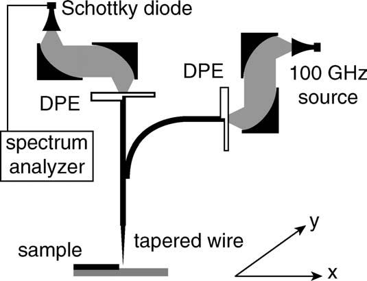
This work turns a sequence of component-level ideas into a complete scanning microscope. A continuous-wave terahertzTerahertz radiation is electromagnetic energy commonly associated with frequencies around 0.1 to 10 THz, between microwaves and infrared, where many materials reveal distinctive propagation, absorption, and imaging behavior. More beam is coupled to Sommerfeld waves on metal wires, routed through a compact guide and concentrated at a tapered needle above the sample. A second wire path carries the response to an external detector. The arrangement is deliberately independent of a particular emitter or receiver: free-space coupling is performed by differential phase elements, allowing the microscope to sit between conventional linearly polarized terahertzTerahertz radiation is electromagnetic energy commonly associated with frequencies around 0.1 to 10 THz, between microwaves and infrared, where many materials reveal distinctive propagation, absorption, and imaging behavior. More hardware. Its central experimental result is a 90 micrometre transition measured across a gold feature at a wavelength near 3 mm, corresponding to approximately one thirty-third of the wavelength.
Featured visual: Image 1 from the Airtable record associated with this publication. Consult the original paper for the authoritative figure caption and interpretation. Source publication.
Visuals are drawn from the Airtable research archive. Figure numbering, rights and interpretation should be checked against the original publication before republication outside this site.
Building a microscope around wire-guided waves
A metal wire supports a Sommerfeld mode whose electric field is radial around the conductor and extends into the surrounding air. At a tapered endpoint, the guided field develops a strong longitudinal component and becomes confined near the apex. The microscope uses that confinement as its local interaction volume. Differential phase elements impose a half-beam phase reversal so that an ordinary Gaussian beam can couple to the radial wire mode on input and be converted back to a detectable free-space field on output.
The source chain covered roughly 75 to 110 GHz and used frequency-multiplied microwave electronics, a horn and off-axis parabolic mirrors. Stainless-steel wires with a diameter of 0.8 mm formed the guides. Calculations based on modal overlap predicted coupling in the range of a few tenths of the incident power, while measured insertion at each phase-element coupler was approximately -5 dB, or about 24%. These values describe the coupling stage itself; the full instrument incurred substantially greater attenuation from propagation, bends and splitting.
A Y-shaped wire junction connected two free-space couplers to a third branch ending in a 4 cm needle. The final 5 mm of the needle was tapered to an apex with a radius near 50 micrometres. The source and detection arms were arranged at right angles to reduce direct reception of the sample’s specular reflection. The sample was moved beneath the probe on motorized stages, while probe height was set manually. Because there was no active height feedback, flatness and positioning remained part of the experimental uncertainty.
Where the terahertz power was lost
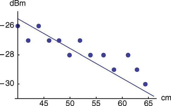
The authors measured the guide rather than treating it as an ideal transmission line. A cut-back experiment over wire lengths from 65 cm to 40 cm gave an attenuation near 0.2 dB per centimetre, about five times the calculated 0.04 dB per centimetre. Surface oxidation or contamination was proposed as a plausible cause because the mode samples the conductor surface. The comparison is useful precisely because it exposes the gap between a clean theoretical wire and an ordinary laboratory wire.
Curvature was even more consequential. Tests with stainless-steel and tungsten wires indicated that bend loss depended mainly on radius rather than on the choice of metal. The microscope geometry required a bend near 20 cm radius, contributing about 30 dB to the loss budget. Straight propagation added roughly 10 dB, and the two free-space coupling stages added about another 10 dB in total. Even before every secondary imperfection was included, attenuation exceeded 50 dB. Nevertheless, the detector could recover signals on the order of tens of picowatts, allowing an image to be formed.
These loss measurements define the engineering priorities clearly. Improving the microscope is not only a matter of sharpening the tip. Straighter routing, cleaner wire surfaces, better-supported guides and lower-loss coupling can increase the field available at the sample and improve the returned signal. The study therefore provides both a proof of imaging and a quantified diagnosis of the instrument.
Subwavelength imaging and its interpretation
The test object was a right-angle gold pattern deposited on glass. During a one-dimensional scan across the metal-to-glass boundary, the signal changed over approximately 90 micrometres using a 10-to-90% transition criterion. That value is close to the physical scale of the tapered apex and corresponds to about λ/33 at 0.1 THz. A two-dimensional scan reproduced the corner geometry, showing comparable localization in both lateral directions.
The image contrast should be read as the response of a longitudinal-field probe interacting with two different local electromagnetic environments, not as a direct optical photograph. The measured transition includes the tip field distribution, probe height, sample properties and mechanical scan. The work does not claim that every material boundary would yield the same 90 micrometre response, and it does not establish a commercial instrument specification. It demonstrates that wire-guided continuous-wave radiation can be delivered to and collected from a localized region well below the diffraction-limited spot size.
For terahertzTerahertz radiation is electromagnetic energy commonly associated with frequencies around 0.1 to 10 THz, between microwaves and infrared, where many materials reveal distinctive propagation, absorption, and imaging behavior. More research, the source-and-detector independence is particularly valuable. The same guided architecture can in principle be paired with different continuous-wave chains, while the near-field branch supplies vector-sensitive local interaction. The project also reflects collaboration between the Institut d’Electronique du Sud and FEMTO-ST, extending earlier joint work on radial polarization and passive wire probes. Support through the French TERASCOPE project placed the microscope within a broader effort to develop practical high-resolution THz instrumentation.
Bibliographic reference
Recommended citation: Guillet, J.-P., Chusseau, L., Adam, R., Grosjean, T., Penarier, A., Baida, F., & Charraut, D. (2011). Continuous-wave scanning terahertzTerahertz radiation is electromagnetic energy commonly associated with frequencies around 0.1 to 10 THz, between microwaves and infrared, where many materials reveal distinctive propagation, absorption, and imaging behavior. More near-field microscope. Microwave and Optical Technology Letters, 53(3), 580-582. https://doi.org/10.1002/mop.25754
Publisher: Wiley. Airtable record: recL2G5VAwmuNaGJW.