Research publication · Non-invasive semiconductor diagnostics
A comprehensive study of the application of the EOP techniques on bipolar devices
Electro-optical probing measures electrical activity inside a semiconductor without placing a metal probe on the node of interest. A near-infrared laser enters through the polished backside of a silicon die, and local changes in carrier population, electric field, absorption and refractive index modulate the reflected light. This paper examines how that signal behaves in bipolar devices, where heavily doped regions and coupled junctions make interpretation more difficult than in many MOS structures. Experiments on discrete NPN transistors and an LM124 operational amplifier compare locations, bias conditions and a defective device, building an evidence-based interpretation rather than treating reflected intensity as a direct voltage measurement.
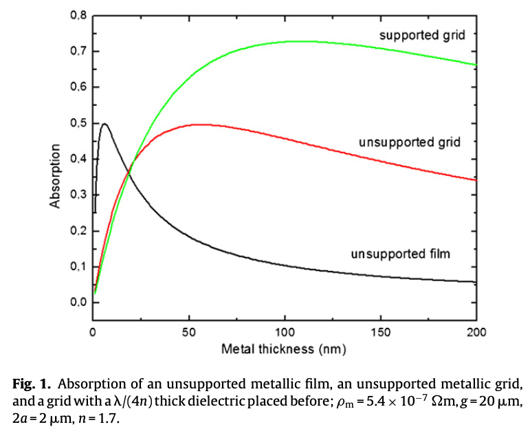
Featured visual: Contextual research figure from âRoom temperature thermopile THz sensorâ. It illustrates a closely related terahertzTerahertz radiation is electromagnetic energy commonly associated with frequencies around 0.1 to 10 THz, between microwaves and infrared, where many materials reveal distinctive propagation, absorption, and imaging behavior. More topic and is not a figure from the publication discussed on this page. Source publication.

Visuals are drawn from the Airtable research archive. Figure numbering, rights and interpretation should be checked against the original publication before republication outside this site.
Backside optical probing under electrical bias
The experiments were performed on the ATLAS platform at the IMS laboratory. A continuous-wave laser at 1350 nm delivered approximately 9.6 mW to the device under test and formed a minimum spot near 6 micrometres in diameter. Silicon is sufficiently transparent at this wavelength for backside access after thinning. An InGaAs PIN photodiode monitored incident power, while an InGaAs avalanche photodiode measured reflected power. Both signals were processed by a lock-in amplifier synchronized with the electrical excitation, and an InGaAs camera helped position the spot over device structures.
The first devices were transistors in a CA3083 NPN array, thinned to about 40 micrometres. The base-emitter junction was held at a constant bias, while the collector-emitter junction received a 480 Hz square pulse with a 500 microsecond width. Measurements were averaged over 100 acquisitions for each voltage condition. The laser was placed under emitter, base and collector contacts so that the spatial dependence of the electro-optical signal could be compared with conventional current-voltage characterization.
Two transistors, Q1 and Q4, showed the expected electrical behavior, while Q3 was already anomalous before sample preparation. In the functional NPN devices, signals under the base and collector were larger than under the emitter. The authors associate the weaker emitter response with its heavier doping, which increases free-carrier absorption and changes how much modulated light returns to the detector. Signal magnitude also changed with collector-emitter bias without simply following the collector current, warning against a one-variable interpretation.
Distinguishing a failed transistor.
Q3 produced weaker electro-optical signals than the functional Q4 at the corresponding probe positions. The difference was especially marked beneath the base. Backside optical inspection also revealed damage in the base-emitter region, supporting the view that the reduced signal was connected to the defective structure rather than merely to instrument drift. The data suggested that more than one affected region might be present, although the study did not claim a complete microscopic identification of the failure mechanism.
This is a valuable but bounded diagnostic result. EOP differentiated the known abnormal transistor and localized a strong contrast near the base, yet signal amplitude depends on doping, geometry, field and optical path. A weak signal is not, by itself, a universal signature of failure. Reference devices, electrical tests and spatial knowledge of the layout remain necessary.
Behavior inside an operational amplifier
The LM124 extended the experiment from an isolated transistor array to a working analog circuit. The operational amplifier was configured as a follower with a 150 ohm output load so that current increased to as much as 5 mA; without the load, no usable EOP signal was observed. A 480 Hz pulse was applied to the non-inverting input, and the study probed transistors Q1, Q4, Q6 and Q13 as well as an internal metal-insulator-semiconductor capacitor.
For the tested PNP devices, the ranking of emitter and base signals was reversed relative to the NPN array. Some responses decreased as input voltage rose and then increased beyond roughly 2.5 V, while other transistors showed a more monotonic decrease. Geometry also mattered: the broader Q6 structure produced a larger response than Q13. These differences reinforce the need to interpret EOP through the specific transistor architecture rather than transfer a simple rule from NPN to PNP devices.
The capacitor supplied an additional physical check. Its reflected signal decreased as the input rose from about 0.5 to 2 V, then increased at higher bias. The behavior was associated cautiously with a transition from depletion toward accumulation. Because the capacitor response can be driven by electric field without transistor current flow, it supports the authors’ conclusion that field-induced carrier redistribution and optical-property changes are major contributors to the measured modulation.
Relevance to advanced electromagnetic diagnostics
The paper establishes that backside EOP can reveal internal activity and failure-related contrast in bipolar technologies, while also showing that quantitative interpretation is complex. It does not provide a universal conversion from reflected optical power to node voltage, and it does not replace destructive physical analysis when the exact defect must be identified. Its strength is the combination of synchronized optical measurement, controlled bias sweeps, spatial probing and comparison between healthy and failed structures.
EOP operates at a near-infrared optical wavelength, not in the terahertzTerahertz radiation is electromagnetic energy commonly associated with frequencies around 0.1 to 10 THz, between microwaves and infrared, where many materials reveal distinctive propagation, absorption, and imaging behavior. More band. Its connection to a broader THz research portfolio is therefore methodological rather than spectral. Both fields rely on non-contact electromagnetic probing, careful separation of material and field effects, lock-in detection and model-based interpretation. For semiconductor reliability, those shared skills support complementary approaches to observing buried structures without front-side electrical access.
The author team links CNES reliability concerns with the IMS laboratory’s optical probing platform and semiconductor failure-analysis expertise. Space and other high-reliability applications motivate non-invasive methods, but the article reports laboratory measurements rather than a qualified in-line inspection process. Its contribution is a more disciplined basis for applying EOP to analog bipolar devices and for recognizing when device physics, not only circuit voltage, shapes the optical signal.
Bibliographic reference
Recommended citation: Rebai, M. M., Darracq, F., Guillet, J.-P., Bernou, E., Sanchez, K., Perdu, P., & Lewis, D. (2014). A comprehensive study of the application of the EOP techniques on bipolar devices. Microelectronics Reliability, 54(9-10), 2088-2092. https://doi.org/10.1016/j.microrel.2014.07.116
Publisher: Elsevier. Airtable record: recHAkhn337pnMomg.