Research publication · Guided millimetre-wave imaging
Guided Reflectometry Imaging Unit Using Millimeter Wave FMCW Radars
Millimetre-wave imaging systems commonly rely on lenses and carefully aligned free-space paths to carry radiation from the radar to the object. This paper investigates a more compact arrangement: an FMCW radarFMCW radar transmits a continuously swept frequency and measures the beat signal produced by delayed reflections, enabling distance, thickness, and depth-resolved imaging with compact coherent hardware. More coupled directly to a thin-walled polypropylene tube that guides the field to the inspection point. Two very different front ends, a 100 GHz III-V radar and a lower-cost 122 GHz SiGe radar chip, are compared through simulation and raster imaging. The guided units resolve millimetre-scale features on a test chart, and a solid immersion lens improves the measured lateral resolution to 2 mm and 1.4 mm respectively. The work demonstrates a laboratory imaging architecture, while also quantifying coupling losses, parasitic reflections and image artefacts that limit immediate deployment.
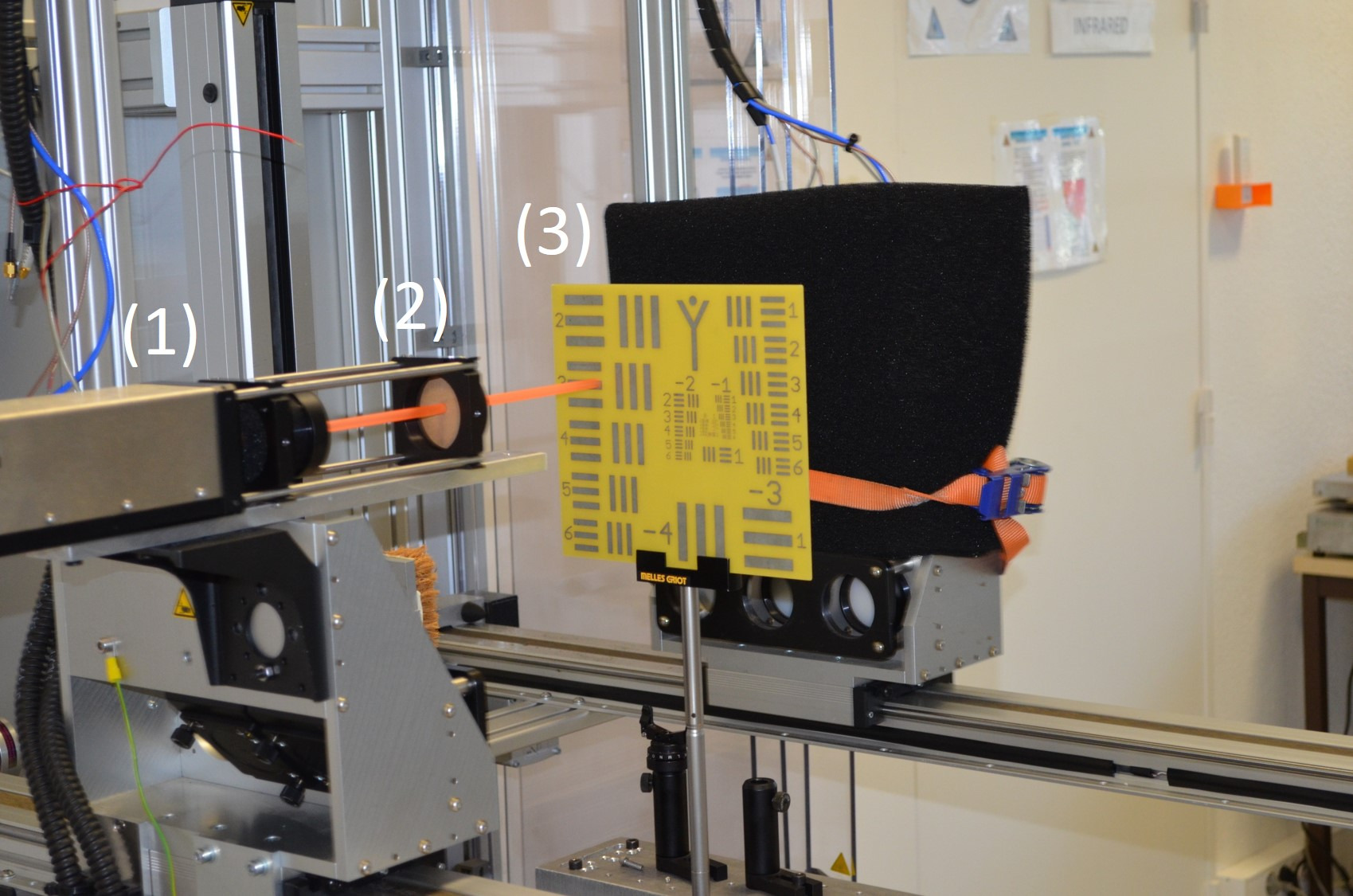
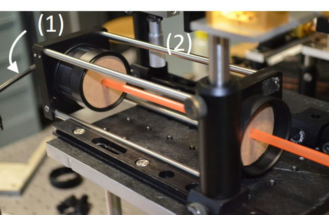
A guided head can place the sensing aperture near a confined or difficult-to-reach surface without reproducing a complete quasi-optical bench around it. The proposed guide is a hollow polypropylene tube with a 3 mm inner radius and a wall thickness of 0.158 mm. Its dimensions place the operating bands in an anti-resonant regime: most energy travels through the air core, while the dielectric wall helps confine it. This is not the same as a conventional metal waveguide carrying a tightly defined single mode. Multiple field components can reach the open end, and a weaker field in the wall can leak outside. Those characteristics create both opportunities for local sensing and practical sources of distortion.
The comparison separates radar cost and integration from image quality. The commercial SynView front end uses a directive conical horn near 100 GHz. The 122 GHz silicon radar uses two-by-two patch arrays with a broader and less symmetric pattern. Full-wave calculations estimated that about 70% of forward power reached the established guided field for the horn configuration, compared with roughly 18% for the patch-based unit. Coupling efficiency alone did not determine resolution: the shape and number of lobes emerging from the tube also controlled what appeared in a short-range image.
Featured visual: Image 1 from the Airtable record associated with this publication. Consult the original paper for the authoritative figure caption and interpretation. Source publication.
Visuals are drawn from the Airtable research archive. Figure numbering, rights and interpretation should be checked against the original publication before republication outside this site.
From antenna pattern to the image at the tube exit
Three-dimensional electromagnetic simulations described how each antenna illuminated the guide and how the field evolved toward its open end. With the SynView horn, the output contained two principal lobes of comparable strength. When the target was placed close to the aperture, both could interact with an edge, producing displaced copies or ghost features. The silicon radar generated a more asymmetric field dominated by one lobe. That reduced the double-image effect but left a directional shadow in the resulting maps. These observations are important because a compact guide does not merely deliver the radar’s nominal frequency band: it becomes part of the imaging transfer function.
The authors tested both arrangements by raster scanning a USAF resolution target. Without an additional lens, the guided 100 GHz unit resolved features at about 4.5 mm with a 5 mm working distance. The 122 GHz unit reached approximately 2.8 mm close to the output. Their usable dynamic ranges were about 27 dB and 28 dB, substantially below the roughly 50 dB available from the free-space SynView instrument. Open-end reflection, coupling loss and unwanted internal returns raise the background against which a weak target reflection must be detected. The silicon chip therefore produced useful images despite lower calculated coupling, but neither guided configuration preserved the complete free-space dynamic range.
To narrow the outgoing field, the researchers integrated a 9 mm diameter hemispherical high-density polyethylene solid immersion lens at the termination. The dielectric element increases the effective numerical aperture and forms a focus a few millimetres beyond the guide. Simulations predicted a spot around 2 mm full width at half maximum for the horn-driven unit at a 2.5 mm working distance. Measurements resolved 2 mm features. For the silicon radar, the reported resolution reached 1.4 mm at approximately 3 mm. The improvement came with sidelobes around -25 dB, so the lens reduced the central spot without eliminating ghost responses from strong edges.
A compact head with measurable engineering trade-offs
The study establishes that a simple polymer guide can replace several free-space coupling elements in a short-range reflectometry experiment. It also shows why the resulting unit must be calibrated as a complete system. Resolution depends on guide diameter, frequency, lens shape, working distance and output-mode distribution. Dynamic range depends on antenna matching and parasitic returns as well as the radar electronics. A quoted frequency or chip specification is therefore insufficient to predict whether a small defect will be visible on a real component.
The external field associated with the guide wall suggests the possibility of peripheral or evanescent-style sensing, but the paper’s verified imaging results concern the field delivered at the termination and the resolution chart. It does not validate a particular industrial defect, production speed or inspection standard. A deployed head would need mechanical control of the stand-off distance, compensation for curved surfaces, material-specific calibration and repeatability studies under vibration and temperature variation. Strong reflection from the open end would also have to be separated from nearby interfaces in the object.
The two front ends reveal a useful design choice rather than a simple ranking. The horn-based III-V system couples more power and starts from a higher free-space performance level, while the silicon radar offers a smaller and potentially less expensive electronic platform. Its broad patch radiation incurs severe coupling loss but, once paired with the guide and immersion lens, still supplies the finer measured chart resolution. A custom transition or antenna designed specifically for the tube could combine more efficient excitation with a controlled single dominant lobe.
Collaboration on a next-stage instrument could accordingly focus on co-designing antenna, hollow guide and terminal optics rather than optimizing them independently. Alternative diameters or wall thicknesses could tune anti-resonant behaviour; a tailored lens could suppress sidelobes; and reference targets could support de-embedding of the guide response. The present article provides the physical and experimental baseline for that work. Its contribution is not a claim of universal portable nondestructive testing, but a demonstrated route toward a compact guided FMCW imaging head with explicitly measured limits.
Bibliographic reference
Recommended citation: Pan, M., Chopard, A., Fauquet, F., Mounaix, P., & Guillet, J.-P. (2020). Guided reflectometry imaging unit using millimeter wave FMCW radars. IEEE Transactions on TerahertzTerahertz radiation is electromagnetic energy commonly associated with frequencies around 0.1 to 10 THz, between microwaves and infrared, where many materials reveal distinctive propagation, absorption, and imaging behavior. More Science and Technology, 10(6), 647-655. https://doi.org/10.1109/TTHZ.2020.3008330
Publisher: Institute of Electrical and Electronics Engineers (IEEE). Airtable record: recMq6xyx5FURCZGn.