Research publication · Guided terahertzTerahertz radiation is electromagnetic energy commonly associated with frequencies around 0.1 to 10 THz, between microwaves and infrared, where many materials reveal distinctive propagation, absorption, and imaging behavior. More reflectometry
Guided terahertzTerahertz radiation is electromagnetic energy commonly associated with frequencies around 0.1 to 10 THz, between microwaves and infrared, where many materials reveal distinctive propagation, absorption, and imaging behavior. More pulse reflectometry with double photoconductive antenna
TerahertzTerahertz radiation is electromagnetic energy commonly associated with frequencies around 0.1 to 10 THz, between microwaves and infrared, where many materials reveal distinctive propagation, absorption, and imaging behavior. More time-domain systems normally use lenses or mirrors to launch a pulse into free space and collect its return. That optical train is manageable on a laboratory bench but awkward when a measurement must be made close to a surface, inside a constrained space or through a flexible guide. This paper develops an optics-free guided reflectometer in which two photoconductive antennas share one active layer and couple directly to a hollow-core silica pipe. One antenna emits the pulse and the other receives its reflection. After 53 mm of guided propagation, the prototype forms an image of a standard resolution target over the 400-550 GHz band.
The contribution is primarily architectural. Direct coupling removes the separate terahertzTerahertz radiation is electromagnetic energy commonly associated with frequencies around 0.1 to 10 THz, between microwaves and infrared, where many materials reveal distinctive propagation, absorption, and imaging behavior. More lenses required by earlier guided systems and creates a compact head for pulse emission and reception. The tested guide is still short, the sample is scanned mechanically and the measured resolution is sub-millimeter rather than microscopic. The work therefore establishes a laboratory basis for close-proximity reflectometry, not a completed endoscope or field-qualified inspection product.
Featured visual: Image 1 from the Airtable record associated with this publication. Consult the original paper for the authoritative figure caption and interpretation. Source publication.
Visuals are drawn from the Airtable research archive. Figure numbering, rights and interpretation should be checked against the original publication before republication outside this site.
Combining a dual antenna with a hollow-core guide
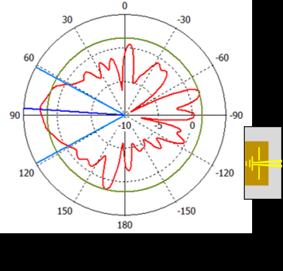
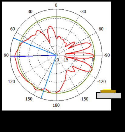
The transceiver was fabricated from an approximately 1.30 micrometer low-temperature-grown GaAs active layer carried at the end of a 180 micrometer thick, 2 mm wide PET cantilever. Two Yagi-Uda photoconductive antennas were patterned side by side. An 800 nm pump pulse illuminated the emitting antenna from the front, while a delayed probe pulse gated the receiving antenna from the rear. The directional antenna geometry was chosen to favor radiation toward the guide and reduce the need for an external focusing component.
Placing two antennas on one small substrate creates direct electrical and electromagnetic coupling that can mask the desired echo. Perpendicular metallic features acting as a wave trap were included in the electrode layout. The authors also measured the response with a metal mirror placed at several distances in 2 mm increments. The early coupling contribution stayed fixed as distance changed, while the delayed mirror return moved and decreased, allowing the two effects to be separated in time.
The guide was a silica pipe with a 3 mm internal diameter and a wall approximately 130 micrometers thick. Its anti-resonant guidance arises because the high-index wall reflects selected frequency ranges back into the air core. The expected wall resonances were near 687 GHz, 1.37 THz and 2.06 THz. Transmission measurements on 201 and 301 mm pipe lengths showed dips close to those values and identified a useful lower band of roughly 350-650 GHz, overlapping the output of the photoconductive transceiver.
Full-wave simulations examined the field between the antenna and waveguide input. Calculated coupling efficiency peaked near 22.8% at 340 GHz and was about 13.2% near 490 GHz. A model with a metal termination showed the emitted pulse entering the core, reflecting from the far end and returning to the receiver after approximately 360 ps. Oscillatory components in the simulated return were associated with higher-order modes and slower propagation in or near the cladding.
The experimental time trace was divided into physically distinct windows. The first 30 ps contained direct antenna cross-talk. Signals from roughly 30 to 250 ps included reflections from the mount and residual coupling structures. The wanted return from the metal plate appeared after about 340 ps. Once the early background was excluded, the guided configuration delivered a reflected signal approximately 12 dB stronger than free-space propagation over the stated 400-650 GHz interval.
Imaging after 53 millimeters of guided propagation
Imaging performance was tested with a 1951 USAF resolution chart positioned within 0.5 mm of the guide output. A motorized stage raster-scanned the target, and a complete time waveform was recorded at each point. The image value was formed by Fourier transforming the return and integrating its magnitude from 400 to 550 GHz. Line profiles across the standard bar patterns showed that group -1 features were resolved, corresponding to approximately 0.707 line pairs per millimeter and a line width near 707 micrometers.
That result is significant because it follows propagation through the compact guide without terahertzTerahertz radiation is electromagnetic energy commonly associated with frequencies around 0.1 to 10 THz, between microwaves and infrared, where many materials reveal distinctive propagation, absorption, and imaging behavior. More focusing optics at either end. It is also bounded by the test conditions. The resolution was influenced by the spectral overlap of antenna and guide, source noise and positioning accuracy. A metal chart provides strong, regular contrast; dielectric defects, rough surfaces or weakly reflecting interfaces will produce different signal levels. No defect-detection probability, long-term repeatability or complex-material trial is reported.
The silica pipe offers access to locations that a conventional free-space bench may not reach, but bending, longer propagation, connector tolerances and sample standoff would all affect performance. The reported guide was straight and 53 mm long in the imaging experiment. Applications involving flexible routing or remote probes require measurements of bend loss, mode conversion and calibration stability. Likewise, moving from a rastered chart to faster inspection would require an appropriate scanning head or array strategy.
The collaboration links terahertzTerahertz radiation is electromagnetic energy commonly associated with frequencies around 0.1 to 10 THz, between microwaves and infrared, where many materials reveal distinctive propagation, absorption, and imaging behavior. More antenna and imaging work in Bordeaux with hollow-core fiber and waveguide expertise in Limoges. That combination is central to the design: neither a directional transceiver nor an anti-resonant guide alone supplies the full reflectometer. A logical next step is tighter mechanical integration, followed by tests on controlled layered or absorbing samples where guided access provides a real advantage. The authors also identify eventual co-integration of transceiver and waveguide as a route to a smaller and more stable probe.
The study demonstrates that a pulsed terahertzTerahertz radiation is electromagnetic energy commonly associated with frequencies around 0.1 to 10 THz, between microwaves and infrared, where many materials reveal distinctive propagation, absorption, and imaging behavior. More echo can be launched, guided, returned and imaged through a direct-coupled dual-antenna assembly. Its measured bandwidth and resolution establish feasibility for the specific guide and metal target. Claims about industrial or biomedicalTerahertz and millimeter-wave technologies offer promising non-ionizing tools for biomedical tissue analysis, particularly for breast cancer research. Their sensitivity to water content, tissue structure, and dielectric contrast can help distinguish... More deployment should remain conditional on further work involving realistic materials, longer and bent guides, robust packaging, faster acquisition and application-specific validation.
Publication and citation
Recommended citation: Pan, M., Cassar, Q., Fauquet, F., Humbert, G., Mounaix, P., & Guillet, J.-P. (2020). Guided terahertzTerahertz radiation is electromagnetic energy commonly associated with frequencies around 0.1 to 10 THz, between microwaves and infrared, where many materials reveal distinctive propagation, absorption, and imaging behavior. More pulse reflectometry with double photoconductive antenna. Applied Optics, 59(6), 1641. https://doi.org/10.1364/AO.381646
Publisher: Optica Publishing Group. Airtable record: recCv2cBVye2iKkK5.